What Is a Signal Converter and How Does It Work?
A Signal Converter connects systems that speak different electrical languages. It transforms voltage, current, frequency, or data into a usable format. This process appears in factories, medical equipment, vehicles, audio systems, and communication networks. A temperature sensor may produce a tiny analog voltage. A controller may require digital numbers instead.
Walt Kester, a respected former Analog Devices engineer, described the ADC as “the bridge between the analog world and the digital world.” His statement captures the converter’s central role. An analog-to-digital converter samples a changing signal, assigns numerical values, and sends those values to a processor. A digital-to-analog converter performs the reverse task. Other converters may change voltage levels, signal standards, or communication protocols.
The operation sounds simple. It is not always simple. Noise can distort a weak input before conversion begins. Limited resolution can hide small changes. Incorrect impedance matching may weaken the signal further. Engineers therefore examine accuracy, sampling speed, bandwidth, isolation, and power requirements together. A converter that works well in a laboratory may behave differently beside motors, relays, or long cables.
This guide explains what a Signal Converter does and how it works. It follows the signal through its main stages, from input conditioning to output transmission. Real equipment examples will make the process easier to visualize. A warm sensor wire, a flashing status light, and a changing waveform can reveal more than abstract definitions. Some applications also involve trade-offs. Better accuracy may increase cost, size, or energy use. That tension deserves careful attention.
What Is a Signal Converter?
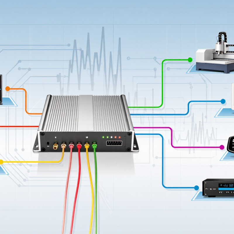
A signal converter is an electronic device that changes one signal format into another. It helps equipment communicate when their electrical languages differ. For example, a sensor may produce a small analog voltage, while a controller needs digital data. The converter translates that measurement into a usable form. Some converters also change voltage levels, current signals, frequencies, or communication interfaces. The purpose is practical: preserve information while making the signal compatible.
Inside, the device may sample an analog waveform, process its value, and produce digital output. Another type performs the reverse operation. Signal isolation can separate two circuits electrically, reducing ground-loop interference and improving safety. In industrial settings, technicians often check input range, output range, resolution, response time, and wiring terminals before installation. A mismatch can create unstable readings.
Small details matter. A long cable may collect electrical noise. Poor grounding may produce a drifting measurement. Shielding helps, but it cannot repair incorrect configuration. A converter also introduces limitations, including delay, conversion error, and signal loss. It is not magic. Even a correctly selected unit can disappoint when calibration is ignored or the power supply is unclean. Reviewing the waveform with a meter or oscilloscope can reveal problems that software hides. In practice, the simplest specification is not always the most reliable choice.
Main Types of Signal Converters
What Is a Signal Converter and How Does It Work?
Signal converters translate one electrical or physical signal into another usable form. They help sensors, controllers, and monitoring systems communicate clearly. In practice, conversion may involve voltage, current, frequency, resistance, or digital data. A temperature sensor might produce a tiny voltage, while a controller expects a stable current signal. The converter bridges that mismatch.
Main Types of Signal Converters
Analog-to-digital converters, or ADCs, change continuous signals into numerical data. Their resolution affects measurement detail. Digital-to-analog converters reverse the process for actuators and control equipment. Signal isolators transfer information while limiting ground loops and electrical interference. This matters near motors, relays, and long cable runs. Frequency converters also change signal frequency, often supporting speed control or accurate pulse measurement. Protocol converters translate data between communication standards, allowing older field devices to work with newer networks.
Industry demand reflects this expanding measurement environment. MarketsandMarkets reported that the industrial sensors market could grow from about 25 billion dollars in 2023 to over 35 billion dollars by 2028. That growth increases the need for reliable signal conversion at the edge. A 2024 report from Grand View Research also identified industrial automation as a major driver for signal-conditioning demand. These figures describe broad markets, not converter sales alone. That distinction matters.
Selection still requires practical testing. Check input range, output accuracy, isolation rating, response time, and installation temperature. A converter can meet its datasheet specifications yet perform poorly beside noisy equipment. I have seen cable grounding receive less attention than resolution. That is an avoidable weakness. Measurements deserve verification under real operating conditions.
Key Components Inside a Signal Converter
A signal converter changes electrical information from one format into another. Its internal design depends on the input and output signals. A temperature sensor may produce a weak voltage, while a control system expects a digital value. The converter bridges that mismatch.
The input stage receives and protects the incoming signal. It may include terminals, surge protection, and impedance matching. A filter then removes electrical noise, such as motor interference or radio-frequency disturbance. The amplifier strengthens low-level signals without adding excessive distortion. This stage needs careful calibration. Too much gain can make a small error look significant.
Many converters use an analog-to-digital converter to sample changing voltage. Its resolution affects how accurately the system represents the original signal. Digital processing can correct scaling, linearity, and alarm thresholds. A digital-to-analog converter performs the reverse task when an analog output is required. Isolation circuits may separate input and output grounds, reducing dangerous ground loops. Power regulation keeps these components stable during voltage changes. Heat matters too. Poor thermal control can slowly shift measurements. The enclosure, connectors, and grounding paths also influence reliability. A compact design is not always the best design; crowded components can make servicing difficult. Even a well-engineered converter may need periodic verification because real environments are rarely as clean as laboratory conditions.
Common Applications and Selection Factors
A signal converter changes information from one electrical form into another usable form. It may convert voltage to current, analog signals to digital data, or one communication format to another. Inside, sensors, filters, amplifiers, and conversion circuits reshape the signal. Isolation may also protect a control system from voltage spikes and ground-loop noise. The process sounds simple, but small design errors can distort important measurements.
Common applications appear in factories, laboratories, energy systems, and building controls. A temperature sensor may produce a weak millivolt signal, while a controller expects a standardized current input. A converter bridges that gap. In a water-treatment cabinet, it can also separate a field device from a monitoring computer. This reduces interference across long cable runs. Audio equipment, medical instruments, and data-acquisition systems use similar methods. Real installations are rarely as clean as diagrams suggest.
Selection should begin with the input and output signal types. Check voltage range, current range, frequency, impedance, and connector requirements. Accuracy matters, but resolution and response time matter too. A slow converter may miss a fast pressure change. A noisy environment may require shielding and electrical isolation. Confirm operating temperature, humidity tolerance, power consumption, and mounting space. Safety certifications and regional requirements should be verified before installation. Calibration records improve traceability. Do not overlook them. In practice, the cheapest unit can become expensive after rewiring, troubleshooting, and repeated calibration. My own preference is to test a converter with the actual sensor and cable length, because laboratory specifications do not reveal every field problem.