
Blog
What Is a Nozzle Cutting Machine and How Does It Work?
A Nozzle Cutting Machine is a precision system designed to cut, shape, or prepare metal nozzles for industrial use. It may combine laser cutting, plasma cutting, or CNC-controlled machining. The chosen process depends on the nozzle material, wall thickness, opening design, and required tolerance. In a factory, the machine can cut stainless steel sheets, copper components, or alloy parts with repeatable accuracy.
The working principle is practical. A digital drawing guides the cutting head along programmed paths. The nozzle focuses energy or directs a cutting jet toward the workpiece. Heat, pressure, or both remove material from the cutting line. Assist gas then clears molten particles from the kerf. Small adjustments matter. A slight change in gas pressure can create rough edges, excess dross, or an uneven opening. Skilled operators inspect the first piece before running a full batch.
Professor John Powell, a recognized laser-cutting specialist, has stated, “The nozzle is the final interface between the cutting process and the material.” This observation highlights its importance. A damaged or misaligned nozzle can reduce accuracy, increase waste, and weaken process stability. Maintenance is not optional. Operators should check nozzle wear, centering, gas flow, and machine calibration regularly. However, no cutting method is perfect. Material reflection, heat distortion, and operator decisions can still affect results. This guide examines how a Nozzle Cutting Machine works, where it performs best, and which practical details deserve closer attention.
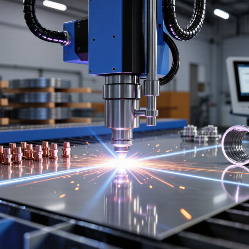
Definition and Main Purpose of a Nozzle Cutting Machine
A nozzle cutting machine is specialized fabrication equipment used to create nozzle openings and connection points in pipes, tanks, and vessel shells. A nozzle is a short pipe section that lets fluids enter, leave, or connect with another system. The machine guides a cutting torch, laser head, or mechanical tool along a programmed path. It can produce round holes, angled openings, and prepared edges for welding. In simple terms, it turns a measured drawing into a controlled cut.
Its main purpose is accuracy and repeatability. An operator enters the pipe diameter, wall thickness, nozzle size, and cutting angle. Sensors or clamps help keep the workpiece stable. The cutting head follows the calculated contour around the curved surface. A clean bevel can reduce later grinding and improve weld preparation. This matters when several nozzles must align with internal pipes or inspection points. Small errors can create large fitting problems.
Real workshop results still depend on setup. Rust, heat distortion, poor clamping, or an incorrect measurement can spoil an otherwise precise cut. Experienced operators check the drawing, confirm the reference line, and inspect the edge afterward. Automated motion does not replace judgment; it makes good preparation more consistent. Some machines cut quickly, but speed alone is not quality. Dross or rough edges may remain, so finishing and dimensional checks are still necessary.
Key Components and Their Functions
What Is a Nozzle Cutting Machine and How Does It Work?
A nozzle cutting machine directs a focused laser beam, plasma arc, or gas stream through a small metal nozzle. The nozzle controls energy, pressure, and cutting direction. Key components include the cutting head, nozzle, focusing lens, gas line, height sensor, and motion system. The lens concentrates the beam onto the material surface. The gas line removes molten metal from the cut. The height sensor maintains a steady gap, often within a fraction of a millimeter. Even a small gap error can create rough edges or incomplete cuts.
According to Fortune Business Insights, the global laser cutting machine market was valued at about USD 6.83 billion in 2023. Its report expects continued growth through 2030, driven by automated metal processing. This growth highlights the nozzle’s practical role. A worn nozzle may distort the gas flow and increase dross. A blocked gas path can also reduce cutting speed. In real workshops, operators sometimes replace parts too late. That habit deserves review.
Tips: Check the nozzle opening before every shift. Keep the lens clean and dry. Match nozzle diameter with material thickness and assist-gas pressure. Test a small sample first. A perfect setting on paper may fail on uneven sheet metal. Record pressure, height, speed, and edge quality for repeatable results.
How the Cutting Process Works Step by Step
A nozzle cutting machine uses a focused energy stream to cut metal, often through plasma, laser, or oxy-fuel technology. The nozzle controls gas flow, heat concentration, and cutting width. A worn nozzle can create a rough edge. Small damage matters.
The process begins with drawing preparation. An operator checks material thickness, alloy, dimensions, and cutting direction. The controller then converts the drawing into tool paths. The machine positions the cutting head above the sheet and sets stand-off distance. Gas passes through the nozzle at a controlled pressure. The energy source starts, pierces the surface, and creates a small entry hole. Cutting speed then stabilizes as the head follows the programmed path.
The nozzle must stay aligned with the workpiece. Poor alignment can widen the kerf and leave dross beneath the plate. Operators inspect sparks, arc shape, and sound during production. A useful practical check is measuring the first cut before running a full batch. According to ISO 9013:2017, thermal-cut edges are assessed through criteria including perpendicularity, surface roughness, and tolerance classes. These checks turn visual judgment into measurable quality control. The 2024 Fortune Business Insights analysis also reports continuing growth in the global laser-cutting machine market, driven by automation and higher precision demands. Yet reports cannot replace shop-floor judgment. Heat reflection, dirty lenses, or unstable gas pressure still cause unexpected defects. Sometimes, the programmed setting is simply wrong.
What Is a Nozzle Cutting Machine and How Does It Work? – How the Cutting Process Works Step by Step
| Step | Process Stage | What Happens | Typical Data or Operating Considerations | Expected Result |
|---|---|---|---|---|
| 1 | Machine Setup | The operator selects the cutting method, installs the appropriate nozzle or cutting head, and loads the material specification into the control system. | Common methods include laser, plasma, waterjet, and oxy-fuel cutting. The choice depends on material type, thickness, required accuracy, and production volume. | The machine is configured for the workpiece and the intended cut profile. |
| 2 | Material Positioning | The sheet, plate, pipe, or fitting is placed on the worktable or fixture. Clamps, supports, or a rotary attachment may be used to prevent movement. | Correct alignment is essential. The workpiece must be stable, accessible to the cutting head, and positioned within the machine's travel range. | The material is securely positioned and referenced to the machine coordinate system. |
| 3 | Program Loading | A digital cutting file is imported or created. The controller converts the design into toolpaths that define the nozzle movement and cutting sequence. | Frequently used file formats include DXF and other CAD/CAM formats. The program may include lead-ins, lead-outs, pierce points, and nesting information. | The machine has a defined path for producing the required opening, contour, or profile. |
| 4 | Nozzle Calibration | The cutting head establishes the correct distance, focus, or stand-off from the material surface. Sensors may detect height or surface position automatically. | Laser cutting commonly requires focal-position control. Plasma and oxy-fuel systems require an appropriate stand-off distance and consumable condition. | The energy or cutting stream is directed at the correct location for a stable cut. |
| 5 | Piercing or Entry | The machine begins the cut by piercing the material or entering from an edge. The controller manages the initial energy, pressure, or flame sequence. | Pierce time and power depend on the cutting process and material thickness. A lead-in can help keep the initial pierce mark away from the finished edge. | A controlled starting point is created without unnecessarily damaging the final contour. |
| 6 | Contour Cutting | The nozzle moves along the programmed path while the cutting beam, arc, waterjet, or flame removes material from the kerf. | Cut quality is influenced by feed rate, energy or gas settings, nozzle condition, material grade, thickness, and machine rigidity. | The desired hole, slot, edge, or three-dimensional nozzle profile is separated from the surrounding material. |
| 7 | Assist Gas or Cutting Medium | A process medium may eject molten material, cool the cut, support combustion, or remove debris from the kerf. | Laser and plasma systems may use compressed gases such as air, nitrogen, or oxygen. Waterjet systems use pressurized water, sometimes with abrasive particles. | Dross, slag, and heat-affected effects are controlled to support a cleaner cut. |
| 8 | Path Completion | The machine completes the programmed contour and applies the programmed lead-out or shutdown sequence. | The controller may reduce energy before stopping and may return the head to a safe position. Closed-loop control can help maintain consistent motion. | The finished part or opening is released from the programmed path. |
| 9 | Part Removal and Cleaning | The operator removes the cut component and clears slag, dross, abrasive, or loose remnants from the work area. | Deburring tools, brushes, compressed air, or secondary machining may be used depending on the required edge finish. | The component is prepared for inspection, welding, assembly, or further finishing. |
| 10 | Quality Inspection | Critical dimensions, edge condition, hole location, taper, and surface finish are checked against the drawing or production specification. | Inspection may use calipers, gauges, templates, coordinate measuring equipment, or optical measurement systems. | The operator verifies whether the cut meets dimensional and quality requirements. |
| 11 | Routine Maintenance | The nozzle, lens or electrode components, gas lines, filters, guides, and work surface are inspected and serviced as required. | Wear, contamination, misalignment, unstable gas flow, and damaged consumables can reduce accuracy and cut quality. | Regular maintenance helps preserve repeatability, safety, and operating efficiency. |
Note: Actual cutting speed, kerf width, maximum thickness, gas pressure, and dimensional tolerance vary according to the cutting technology, material grade, machine configuration, and process settings.
Materials, Applications, and Common Uses
What Is a Nozzle Cutting Machine and How Does It Work?
A nozzle cutting machine produces precise openings, edges, and profiles in small nozzle components. It may use CNC turning, laser cutting, abrasive wheels, or fine drilling tools. The method depends on the material, wall thickness, and required tolerance. During operation, the machine secures the workpiece, follows programmed coordinates, and removes material in controlled passes. Coolant or air can reduce heat and clear small chips.
Common materials include stainless steel, brass, aluminum, engineering plastics, and technical ceramics. Metals suit fuel, water, coating, and compressed-air systems. Plastics are useful for chemical handling because they resist corrosion and remain lightweight. Ceramics tolerate extreme heat, although they can crack under sudden pressure. Small details matter.
These machines support agricultural sprayers, industrial cleaning equipment, welding systems, medical fluid devices, and precision coating lines. They also make replacement nozzles and prototype parts. In a workshop, operators check hole diameter with gauges and inspect the outlet under magnification. A clean edge helps create a stable spray pattern. A rough edge may cause uneven flow, extra noise, or early wear.
Material selection is not always straightforward. A harder material may last longer but require slower cutting. Heat can distort polymer parts, while excessive force can damage ceramics. Even experienced technicians sometimes adjust the program after testing the first sample. That step is easy to underestimate. Surface finish, alignment, pressure, and fluid viscosity must be checked together.
Safety Requirements and Routine Maintenance
What Is a Nozzle Cutting Machine and How Does It Work?
A nozzle cutting machine shapes or trims nozzles with controlled heat, abrasive force, or a focused cutting stream. The nozzle guides energy and material flow, so even a small defect can affect accuracy. Operators should inspect the work area before powering the machine. Remove loose tools, oil, and flammable materials. Keep guards fitted and confirm that emergency stops operate correctly. Wear eye protection, hearing protection, cut-resistant gloves, and suitable work clothing. Use local extraction when cutting creates fumes or dust. Never place hands near the cutting head during operation. Lock out the power before clearing a jam.
Routine maintenance protects both safety and cutting quality. Check the nozzle opening for chips, blockage, uneven wear, or heat damage. Clean it with the approved tool, not a sharp object that may enlarge the opening. Inspect cables, hoses, fittings, and shields for cracks or leaks. Verify air, gas, or coolant pressure against the machine’s service instructions. Strange noise matters.
A practical maintenance log should record inspections, cleaning, part replacement, and unusual results. This creates traceable evidence for supervisors and qualified technicians. A checklist is useful, but it is not perfect. Dust can hide a small crack, and rushed inspections can miss it. Stop the machine when performance changes unexpectedly. Only trained personnel should adjust settings or repair internal components.
