
Blog
How to Install a 3 Way Switch Dimmer in 2026?
Installing a 3 Way Switch Dimmer in 2026 requires more than replacing one wall switch. A three-way circuit lets two locations control the same light, while the dimmer must work correctly with that wiring arrangement. The right approach combines careful identification, compatible equipment, and respect for current electrical requirements.
Safety comes first. Turn off the circuit breaker, then verify the wires with a reliable voltage tester. Do not trust the switch position alone. Older homes may contain confusing wire colors, crowded boxes, or wiring that does not match modern expectations. A clear photo and careful labeling can prevent an expensive mistake. Still, photos are not enough. Confirm each conductor’s function before disconnecting anything.
This guide explains how to choose a compatible 3 Way Switch Dimmer, identify the common and traveler wires, and test the finished installation. It also discusses LED bulb compatibility, neutral-wire considerations, box depth, grounding, and flicker problems. Details matter here. A dimmer that works with incandescent lamps may perform poorly with LEDs. Some smart models also require a neutral connection or a matching companion switch.
I have seen installations fail because the traveler wires were treated like ordinary load wires. That small assumption caused repeated troubleshooting. It is easy to overlook. If the circuit remains unclear, stop and consult a licensed electrician familiar with local codes. Manufacturer instructions and regional requirements should guide the final decision, especially in older properties. A successful installation should feel quiet, stable, and predictable—not warm, buzzing, or uncertain.
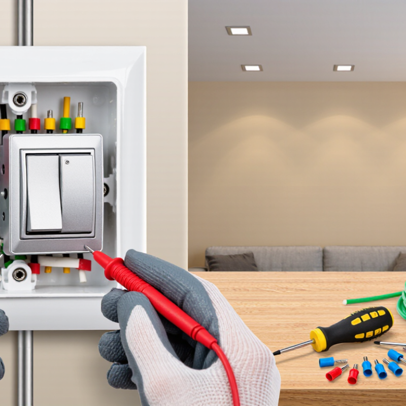
Safety Rules and Compatibility Checks for a 3-Way Dimmer
How to Install a 3-Way Switch Dimmer in 2026?
Safety Rules and Compatibility Checks for a 3-Way Dimmer
A three-way dimmer controls one light from two locations. Power must be off at the breaker before removing the wall plate. Verify the circuit with a two-pole voltage tester, not only the switch position. The National Fire Protection Association reported an average of 32,620 U.S. home fires involving electrical distribution or lighting equipment each year from 2015 to 2019. Those fires caused about 470 deaths annually. A loose terminal is a small detail with serious consequences.
Check the dimmer’s wiring diagram and load rating carefully. It must support three-way operation, the lamp type, and the total wattage. Some LED lamps need a compatible dimmer and a minimum load. Confirm whether a neutral wire is required. Do not trust wire color alone; identify line, load, travelers, and ground with testing. The electrical box should also have enough space for the device and conductors. Crowded boxes can damage insulation.
Install the dimmer at one control location, then connect the second location with the correct companion switch. Never connect a standard switch by guesswork. I have seen travelers confused with the common wire during rushed repairs. That mistake can leave the light working but the circuit unsafe. Secure every terminal, fold wires gently, restore power, and test both switches at low and full brightness. If readings seem unexpected, stop and consult a qualified electrician.
Tools, Materials, and Wiring Terms You Need to Know
How to Install a 3 Way Switch Dimmer in 2026?
Before touching a 3-way dimmer, gather insulated screwdrivers, a non-contact voltage tester, wire strippers, pliers, and a flashlight. Use approved wire connectors, electrical tape, and a compatible dimmer rated for your lamp load. A sturdy wall box also matters. Loose boxes make installation frustrating.
Turn off the breaker and verify every wire with the tester. Do not guess. The line wire brings power from the panel. The load wire carries power to the light. Traveler wires connect the two switch locations, while the ground wire provides a safer fault path. The neutral wire usually returns current, although many older switch boxes do not contain one. Check the dimmer instructions before buying materials.
Label each conductor before disconnecting anything. This small step prevents confusion later. My practical lesson is simple: wire color alone is not reliable, especially after previous repairs. A common terminal often differs from traveler terminals, but layouts vary. Take a clear photo, then compare it with the wiring diagram. Never work on energized wiring, and stop if the box contains damaged insulation, heat marks, or unfamiliar conductors. Local electrical rules may require a qualified electrician, particularly in older homes. A careful installation may still need testing with the light at low and full brightness. Some LED lamps flicker, even when the wiring appears correct.
How to Install a 3-Way Switch Dimmer in 2026?
This chart shows common copper conductor sizes and their typical 60°C ampacity values for residential branch-circuit planning. A 3-way dimmer must be compatible with the circuit voltage, load type, and circuit rating. Always verify local electrical codes and the device instructions before installation.
Key Wiring Terms
Line: The energized conductor supplying power. Load: The conductor going to the light fixture. Traveler: One of the interconnecting conductors between the two 3-way switch locations. Ground: The protective bonding conductor. Turn off the breaker and confirm the circuit is de-energized before handling any wiring.
How to Turn Off Power and Identify the Existing Wires
Before installing a three-way switch dimmer, turn off power at the circuit breaker, not only at the wall switch. Tell everyone nearby that the circuit is being serviced. If possible, place a note on the panel so nobody restores power accidentally. Never rely on the switch position. The box may still contain energized wires.
Use a properly rated voltage tester on the existing switch, each wire, and the metal box if present. Test the tester on a known live outlet before and after checking the circuit. This simple step catches a failed tester. Remove the cover plate, then photograph the wiring before disconnecting anything. Label each conductor with tape. In a three-way circuit, one wire is usually the common, while two others are travelers. Ground is normally bare or green, but insulation colors are not proof of function.
Look for the common wire attached to the darker terminal, but confirm its role from the circuit layout. Do not depend on memory or wire color alone. Older wiring can be confusing. A neutral wire may be absent from one box, and some dimmers require one. Check the installation instructions for the exact wiring requirements. Keep loose wires separated, and do not touch exposed copper while power is restored for testing. If the tester gives an unexpected reading, stop and investigate. I would rather pause than guess. When labels are unclear, insulation is damaged, or multiple circuits share the box, contact a qualified electrician. Safety is not a good place for improvisation.
| Step | Task | What to Do | Wire or Test Information | Key Safety Check |
|---|---|---|---|---|
| 1 | Confirm the circuit type | Verify that the light is controlled from two switch locations. A standard three-way circuit has two switches and no ordinary on/off switch with an “ON” or “OFF” position. | Each three-way switch normally has one common terminal, two traveler terminals, and one ground terminal. | Do not begin if the wiring configuration is unclear, damaged, overheated, or lacks a grounding conductor where one is required. |
| 2 | Gather suitable tools | Prepare a listed three-way dimmer, insulated screwdrivers, a non-contact voltage tester, a two-pole voltage tester or multimeter, wire connectors, electrical tape, and a flashlight. | Use a dimmer rated for the lighting load and compatible with the lamp type. Check the installation instructions for minimum and maximum load ratings. | Turn off power before removing the wall plate or touching any conductor. |
| 3 | Turn off the power | At the service panel, switch off the circuit breaker controlling the light. If the correct breaker is unknown, turn off the main disconnect only when it is safe and appropriate to do so. | Do not rely on the wall switch position as proof that the circuit is de-energized. | Keep the breaker off and prevent anyone from restoring power while work is in progress. |
| 4 | Test before contact | Test the existing switch, wires, and the metal electrical box if present. Test the voltage tester on a known energized source before and after checking the circuit. | Check between hot and neutral, hot and ground, and neutral and ground where those conductors are accessible. | A non-contact tester is a screening tool; use an adequately rated contact tester or multimeter to confirm zero voltage. |
| 5 | Document the existing connections | Remove the wall plate and photograph the wiring before disconnecting anything. Label each wire by the terminal it was connected to. | Identify the wire on the differently colored common screw separately from the two traveler wires. Do not depend only on insulation color. | Do not remove wires until the circuit has been tested and the connections have been documented. |
| 6 | Identify the common wire | Find the conductor connected to the common terminal of the existing three-way switch. The common terminal is usually a different color from the two traveler terminals. | The common wire may carry incoming line power or switched power to the light, depending on which switch box is being modified. | Wire colors and cable arrangements can vary. Terminal location and circuit testing are more reliable than color alone. |
| 7 | Identify the travelers | Locate the two wires connected to the matching traveler terminals. These wires run between the two three-way switch locations. | Travelers are interchangeable on a standard three-way switch, but they must not be connected to the dimmer’s common terminal. | Keep the traveler pair together and preserve the original cable routing. |
| 8 | Check the neutral and ground | Look for a neutral conductor in the box if the dimmer requires one. Identify the grounding conductor or grounded metal box where applicable. | Neutral conductors are commonly white, but a white wire may be repurposed in some older installations and must be verified. Grounding conductors are commonly bare or green. | Never use a grounding conductor as a neutral, and never disconnect or remove a required grounding connection. |
| 9 | Check dimmer compatibility | Confirm that the dimmer is specifically designed for three-way operation and that the existing companion switch is compatible with the dimmer’s wiring method. | Some dimmers require a neutral; others do not. Some require a specific companion control instead of a standard three-way switch. | Follow the wiring diagram supplied with the exact dimmer. Do not assume all three-way dimmers use the same terminals. |
| 10 | Disconnect the existing switch | With power verified off, loosen the terminal screws and remove the wires. Keep the common wire clearly labeled. | Do not place more than the permitted number of conductors under a terminal. Use approved connectors when joining wires. | Inspect for loose strands, scorched insulation, corrosion, or wires that are too short to make a secure connection. |
| 11 | Connect the three-way dimmer | Connect the labeled common wire, the two traveler wires, the grounding conductor, and the neutral if required by the dimmer’s instructions. | Terminal names may include common, line, load, traveler, neutral, and ground. “Line” and “load” must be connected as specified by the installation diagram. | Make tight, approved connections with no exposed copper extending beyond the terminal or connector. |
| 12 | Secure the dimmer in the box | Fold the wires carefully into the electrical box and attach the dimmer without pinching or sharply bending the conductors. | The device should sit straight and the mounting screws should be secure without damaging the box or device yoke. | Do not force an overcrowded device into the box. Box-fill requirements may limit the number and size of conductors allowed. |
| 13 | Install the wall plate | Fit the wall plate after confirming that no bare energized part is exposed and that the device is properly aligned. | Use a plate suitable for the device shape and tighten screws evenly without cracking the plate. | Keep the wall plate installed during normal use to reduce accidental contact with wiring. |
| 14 | Restore power and test | Restore power at the breaker. Test the dimmer at low, medium, and high settings from both switch locations. | Confirm that the light turns on and off from either location and that brightness changes smoothly without abnormal noise or flicker. | Turn power off immediately if there is sparking, heat, buzzing, a burning smell, tripped protection, or unexpected operation. |
| 15 | Perform a final inspection | Check that the device is firmly mounted, the plate is secure, and the dimmer does not become unusually warm during normal operation. | Recheck the lamp’s load type and total wattage if flicker, limited dimming range, or shutdown occurs. | Stop work and consult a qualified electrician when the circuit has aluminum wiring, multiple circuits in one box, missing grounding, heat damage, or uncertain connections. |
| Important: Electrical requirements vary by location and installation age. Follow the applicable electrical code and the exact instructions supplied with the dimmer. When the circuit cannot be positively identified or de-energized, do not proceed. | ||||
Step-by-Step Installation of a 3-Way Switch Dimmer
How to Install a 3 Way Switch Dimmer in 2026?
Step-by-Step Installation of a 3-Way Switch Dimmer
Before touching the wiring, switch off the circuit breaker and confirm the circuit is dead with a voltage tester. Do not rely on the wall switch alone. Remove the cover plate, photograph the existing connections, and label the common wire separately from the traveler wires. A three-way dimmer usually replaces one switch, while the other remains a compatible three-way switch. However, wiring layouts differ. Check the dimmer’s instructions and confirm that the light fixture supports dimming.
Loosen the old switch terminals and transfer each wire to the correct terminal. Connect the common wire to the dimmer’s common terminal, then attach the traveler wires to the remaining terminals. Join the ground wire securely. Some installations also require a neutral connection, so inspect the box before buying a replacement. Fold the wires carefully, fasten the dimmer, and reinstall the cover plate. Restore power and test the light from both locations. I once assumed two wires were travelers because they looked identical. The labels prevented a costly mistake.
Tips: Keep the breaker off while working. Use a properly rated tester. Tighten terminal screws firmly, but avoid crushing the wire. If the box is crowded, stop and reassess. Flickering, buzzing, heat, or a nonworking second switch signals a wiring problem. Turn the breaker off again and contact a licensed electrician when the circuit does not match the instructions.
Testing the Circuit and Troubleshooting Common Problems
How to Install a 3 Way Switch Dimmer in 2026?
Testing the circuit is the safest part of installing a three-way dimmer. Turn off the breaker before removing the wall plate. Do not trust the switch position alone. Use a properly rated voltage tester on every wire. Test the wires against the grounding conductor and the box, if it is metal. Confirm that the tester works on a known live circuit before checking the disconnected wires. This small habit prevents false confidence.
A three-way dimmer usually works with one compatible companion switch, not two ordinary dimmers. Photograph the existing wiring before disconnecting anything. Mark the common wire clearly, because its position matters more than its color. After installation, restore power and test both switches at low and full brightness. If the light stays on, flickers, or responds from only one location, switch off the breaker again. Check loose terminals, reversed traveler wires, and an unsuitable lamp. I once focused on wire color and missed a loose terminal. That was a poor assumption.
Tips: Keep wires folded neatly inside the box without forcing them. Check the dimmer’s load rating and wiring instructions. If the tester gives confusing readings, stop and call a licensed electrician. A warm faceplate, buzzing sound, burning smell, or repeated breaker trip is not a minor inconvenience. It signals a fault that needs professional testing. Take notes during each check. They expose mistakes that memory often hides.
